

Working Principle Of Brushless Generator
Aug 04, 2026
Leave a message

Complete working principle of a brushless generator
Compared to brushed models, the core difference is that the carbon brush and slip ring contact conductive structure are eliminated, relying on electromagnetic induction for air transmission and excitation. The overall structure is divided into a two-stage structure of the main generator and excitation generator, converting mechanical energy step by step into electrical energy.
1. Core components
1. Main stator: The fixed winding on the outer side of the body, which ultimately outputs electrical energy externally
2. Main rotor: The rotating shaft component with a built-in excitation coil that generates a working magnetic field
3. Exciter Stator: A small fixed coil that generates an initial excitation magnetic field
4. Exciter rotor: Coaxial synchronous rotating coil, inducting and generating excitation AC current
5. Rotary rectifier: installed at the rotor end, rotates with the shaft to convert AC to DC
6. Shaft power mechanism: Diesel/gasoline engines drive the entire rotor to rotate
2. Core Principles and Core Logic
Abandoning the carbon brush sliding power supply method, it uses coaxial rotary induction onboard rectification to supply DC power to the rotating main rotor coil to create a magnetic field, which then cuts the magnetic field lines to complete power generation.
Energy flow: mechanical energy→ excitation electrical energy→ rotating magnetic field→ induced AC power→ external power supply
3. Step-by-step workflow
Step 1: Establish the initial excitation magnetic field
After the unit starts, the control system applies a weak current to the exciter stator
When the fixed coil is energized, a stable static magnetic field is formed inside.
Step 2: The excitation rotor rotates to induce power
The power drives the entire spindle to operate, and the exciter rotor and spindle rotate synchronously at high speed
The rotor coil continuously cuts the magnetic induction lines of the exciter stator, inducing alternating current.
Step 3: Rotate and rectify the current to convert it into DC excitation power
The induced AC power is sent to the rotary rectifier mounted on the coaxial axis
The rectifier module converts AC power into steady DC power, which is directly supplied to the coaxial main rotor excitation coil.
Step 4: The main rotor forms a rotating strong magnetic field
When DC current enters the main rotor winding, the iron core is magnetized, forming a strong magnetic field with N and S poles
As the rotor keeps rotating, the magnetic field spins at high speed.
Step 5: The main stator cuts the magnetic flux line to generate electrical energy
The main stator windings at rest on the periphery are continuously swept by the rotating magnetic field
Based on the principle of electromagnetic induction, high-power three-phase AC is induced inside the stator coil.
Step 6: After voltage regulation and voltage regulation, output externally
The produced AC power is regulated by the voltage regulation module and finally outputs through the wiring port, driving various electrical loads.
4. Key Differences Between Brushless and Brushed
Please refer to the following article. Today, we will discuss the working principles of brushed and brushless generators
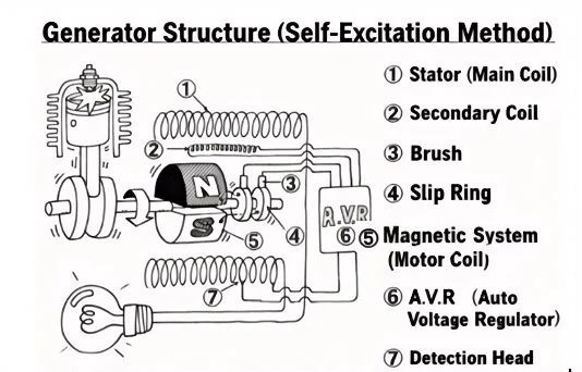
5. Simplified text structure diagram
6. Shorthand Mnemonics
Two-stage brushless structure with excitation induction and remote transmission
Rotating rectifier to DC, rotor magnetization to magnetic field
Stator cutting generates electricity, stabilizing voltage output for stable power supply